
Alumex Metals / Profile machining
Extrusions
we machine.
From frame members to glazing retainers and connection profiles. Contract machining from your released drawings.
Profile families
Find the section you work with.
Explore the component, its role and the machining details to include in your RFQ.
01 / Main frame profiles
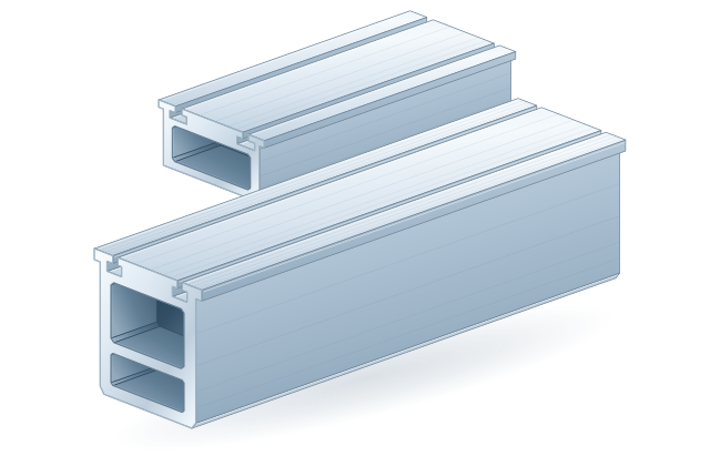
Mullions & transoms
The vertical and horizontal members that form the curtain wall frame. Their extrusion section carries the connection, glazing and gasket details.
Machining scope to quote
- Cutting to the scheduled member length
- Connection and shear-block hole patterns
- Countersinks, end notches and access features where detailed
Include with the RFQ
Section drawing, handed part drawing, reference faces, end conditions and the approved connection detail.
Quote this profileTypical profile types
Vertical mullions · Horizontal transoms · Corner profiles · Reinforced sections
Where it fits
Transom ends engage with the connection blocks fixed to the mullion. Machined features must line up with the released joint detail.
02 / Exterior glazing retainers
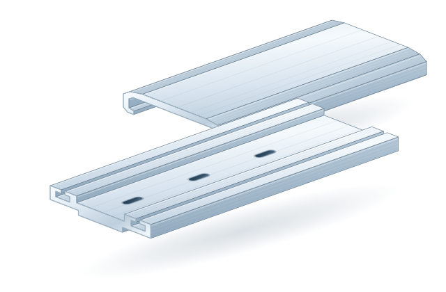
Pressure plates & caps
Two distinct extrusions at the outside of a captured curtain wall. The pressure plate retains the glazing through the specified gasket arrangement; the cover conceals its fixings.
Machining scope to quote
- Cutting plates and covers to their separate schedules
- Pressure-plate fastener holes and specified drainage slots
- Cover weep holes or end details where the drawing calls for them
Include with the RFQ
Plate and cap part IDs, orientation, hole and drainage details, finish and visible-face protection.
Quote this profileTypical profile types
Horizontal pressure plates · Vertical pressure plates · Snap-on face covers
Where it fits
The pressure plate fastens through the thermal isolator to the frame. The face cover clips over the installed plate.
03 / Head, jamb and base interfaces
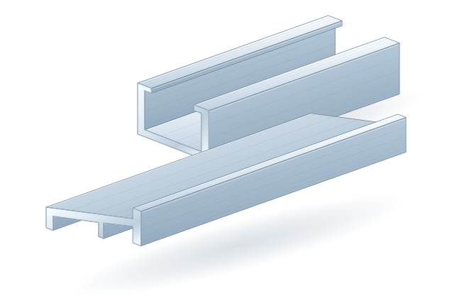
Perimeter & sill profiles
Profiles used where the framing meets the opening: heads, jambs, sills, receivers and related perimeter sections.
Machining scope to quote
- Straight or angled cuts to the part schedule
- Specified end notches and attachment holes
- Slots, pockets and drainage details from the released drawing
Include with the RFQ
Opening location, orientation, end-treatment details, mating profiles and any finish-sensitive surfaces.
Quote this profileTypical profile types
Heads & jambs · Sill sections · Receivers · Glazing adaptors
Where it fits
Perimeter conditions change with the opening and connection design. A head member may need an end notch while another member uses a different fixing pattern.
04 / Hollow architectural sections
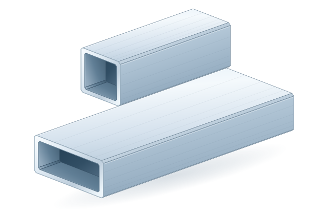
Tubes & box sections
Square and rectangular hollow extrusions used in architectural components and subassemblies. Each wall and internal cavity affects tool access and workholding.
Machining scope to quote
- Cutting and end treatment to the drawing
- Drilled or tapped features on specified faces
- Milled slots and access openings, subject to section review
Include with the RFQ
Outside section, wall thickness, stock length, feature location, tool access and required inspection.
Quote this profileTypical profile types
Square tube · Rectangular tube · Multi-cavity box sections
Where it fits
Machining can prepare a hollow profile for its specified connection, fixing or mating component. The assembly drawing defines the interfaces.
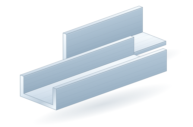
05 / Open architectural sections
Angles & channels
Open L and U sections, trim channels and related extrusions used for supports, edges and interfaces within an OEM assembly.
Machining scope to quote
- Cutting parts from the specified extrusion
- Fixing holes, slots and countersinks where detailed
- End notches and clearance features after fit review
Include with the RFQ
Leg or flange dimensions, wall thickness, handed view, contact faces and the machining drawing.
Quote this profileTypical profile types
Equal & unequal angles · U channels · Trim & adaptor channels
Where it fits
Open sections need a clear datum and part orientation so cuts, holes and notches align with the component they attach to.
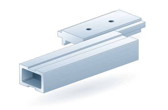
06 / The details between members
Connection profiles
Short sections and sleeves that connect or align larger frame members. Their engagement and fixing positions are specific to the OEM system.
Machining scope to quote
- Cutting short pieces to the connection schedule
- Attachment holes, countersinks or tapped features as specified
- Notches, reliefs and access details after review
Include with the RFQ
Mating section, connection drawing, part quantity, fastener detail and required fit or inspection criteria.
Quote this profileTypical profile types
Extruded shear blocks · Splice sleeves · Connection sections
Where it fits
A shear block fits inside the horizontal member at its connection to the mullion. A splice sleeve relates to the vertical mullion joint and its designed movement allowance.
Have a different section, PVC profile or thermal assembly? Send the section drawing for a machining fit review.
From individual profiles to a system
How the layers
come together.
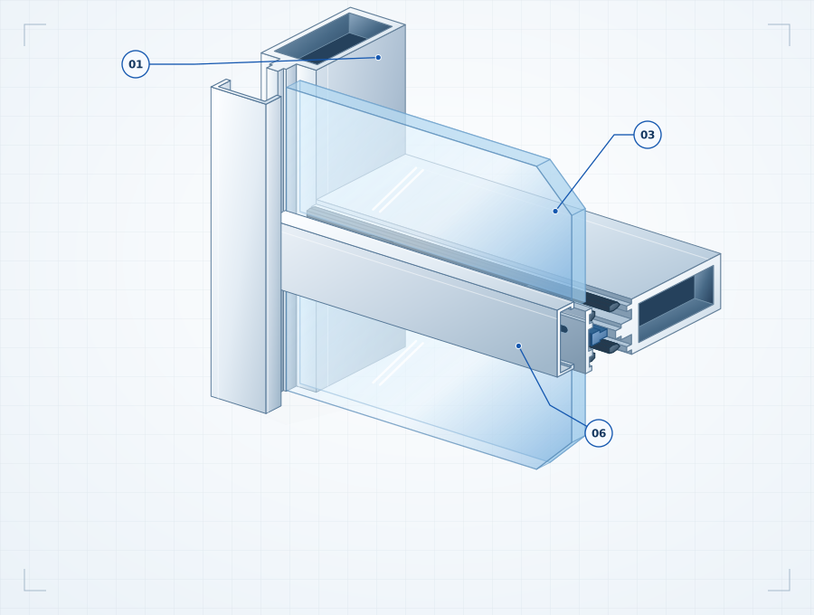
A representative captured curtain wall detail. Separate the layers to see where the machined aluminum parts sit within the assembly.
Reading the assembly
- 01
Rear framing
The mullion and transom form the frame. Cut lengths and connection features locate the joint.
- 02
Interior gaskets
Gaskets seat in the frame reglets and form the inner glazing contact.
- 03
Glazing
The glass is supported by the specified glass chairs and setting blocks.
- 04
Thermal isolator
The specified isolator sits between the frame nose and the exterior pressure plate.
- 05
Pressure plate & gaskets
The plate fastens to the frame and retains the glass through the exterior gaskets.
- 06
Snap-on face cover
The cover clips over the pressure plate. Its drainage detail is separate from the plate’s slots.
The agreed cutting, drilling, tapping and milling of your aluminum profiles. Glazing, gaskets, system design and installation are shown here to explain the assembly context.
About this assembly example
The frame connection and glazing sequence were studied from Acro’s 3000 Series installation manual, including its horizontal-to-mullion connection and captured-glazing details. These are original representative illustrations, not Acro part drawings or an Alumex curtain wall system.
Acro 3000 installation referenceBefore you release the parts
A profile drawing is
the starting point.
Pair the extrusion section with the machining drawing, quantity and required release date. Call out critical datums, handed parts, visible surfaces and inspection requirements.
Request for quote
Send your drawings and cut list.
Include the profile, quantities by release and when the first batch is due.